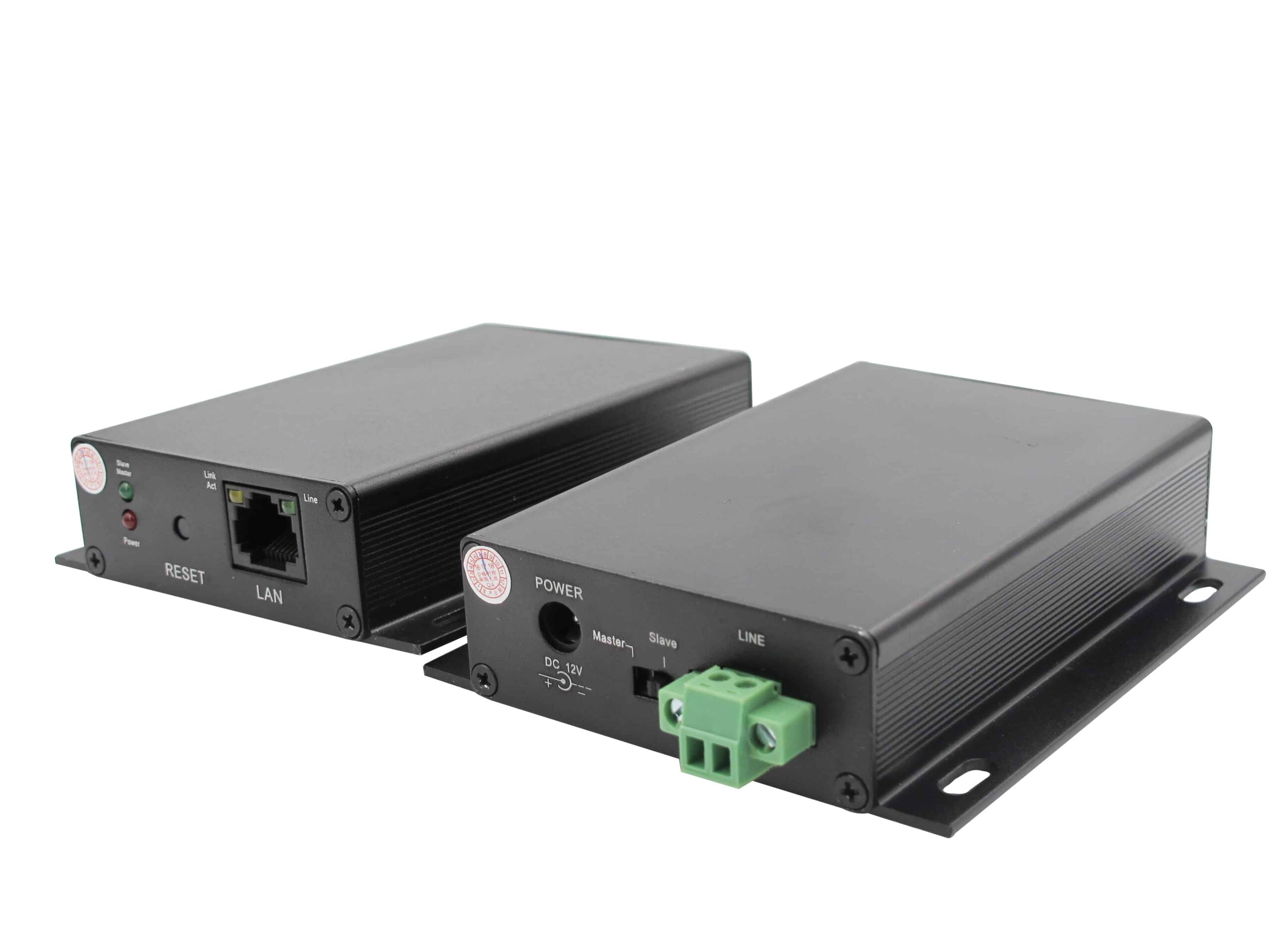
High Distance LAN extender (ethernet) extender over copper UTP cables
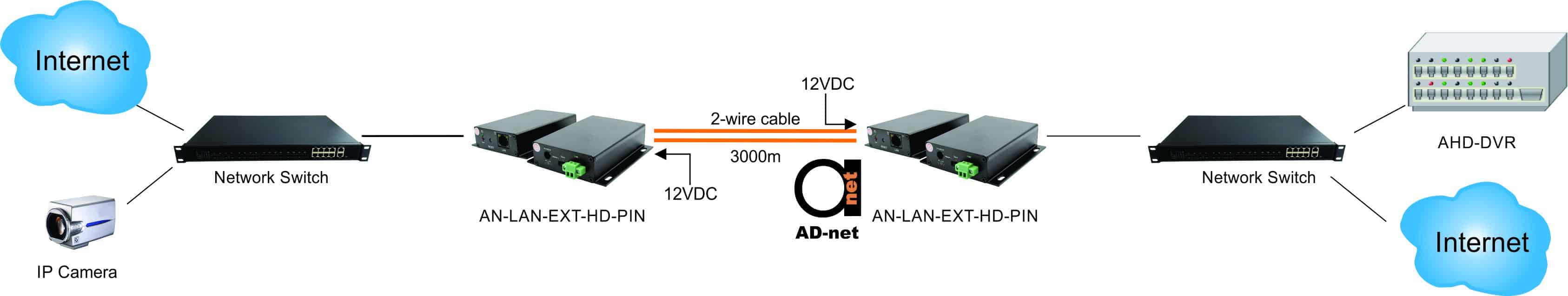
AN-LAN-EXT-HD-PIN Ethernet Extender is a network signal extension device, which consists of remote unit and local unit. It can transmit network signal over 2-wire such as Cat5, telephone lines or coaxial cables, etc. The max distance can reach 3,000m and max bandwidth can reach 148Mbps. Meanwhile, it also can transmit telephone signal when transmitting network signal (adding an additional splitter).
- Max transmission distance reach 3,000m
- Max transmission rate reach 148Mbps
- Support audio signal transmission over cables simultaneously
- Plug and play, transparent transmission, network rate adaptive
- Cat5, telephone lines or coaxial cables for choices
|
Categories |
Description |
|
|
Power |
Voltage Range |
12VDC±10% |
|
Power Consumption |
<4W / PC |
|
|
Transmission Rate |
Up link 74Mbps/ Down link 74Mbps |
Max 148Mbps |
|
Protection |
Transmission Channel Lightening |
4KV 10/700us, common mode lightning: Level 4 |
|
1KV 10/700us, differential mode lightning: Level 1 |
||
|
Executive Standard: IEC61000-4-5 |
||
|
Product Electrostatic Protection |
1a contact discharge Level 4 |
|
|
1b air discharge Level 4 |
||
|
Executive Standard: IEC61000-4-2 |
||
|
Reliability |
MTBF |
>30,000 hours |
|
Physical Characteristic |
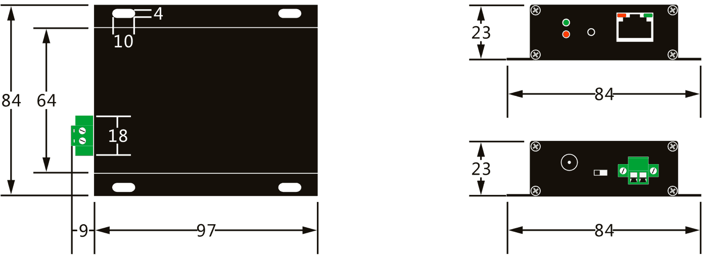
Dimensions (L × W × H) |
97mm×84mm×23mm |
|
Material |
Aluminum |
|
|
Net Weight |
140g / PC |
|
|
Operating Environment |
Working Temperature |
-20℃~60℃ |
|
Humidity |
<95% (Non-condensation) |
|
Cable tips
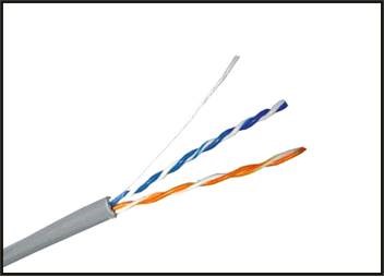
Telephone Line: Category 3 or above
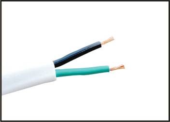
Power Line: RVV, RVS, RVVP, RVB 2×0.5mm2
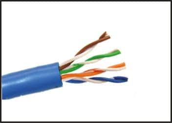
UTP Cable: Category 5 or above
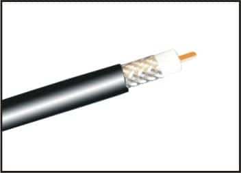
Coaxial Cable: RG59 or above
Accessories Spec
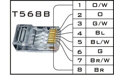
RJ45 port by EIA / TIA568B
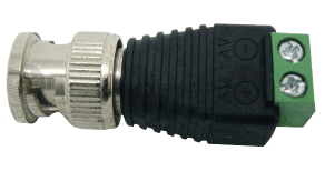
BNC/2-wire Converter (Optional)
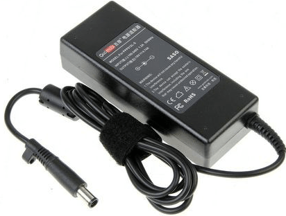
Power Adapter by 12VDC/1A, 5mm female power port (Optional)
Dimension
Transmission Rate and Loss:
Ethernet Extender supports high speed network data signal transmission. Transmission rate will differ in line with different cables. With the cable length increasing, the transmission rate will decrease accordingly. Please refer to the following testing data.
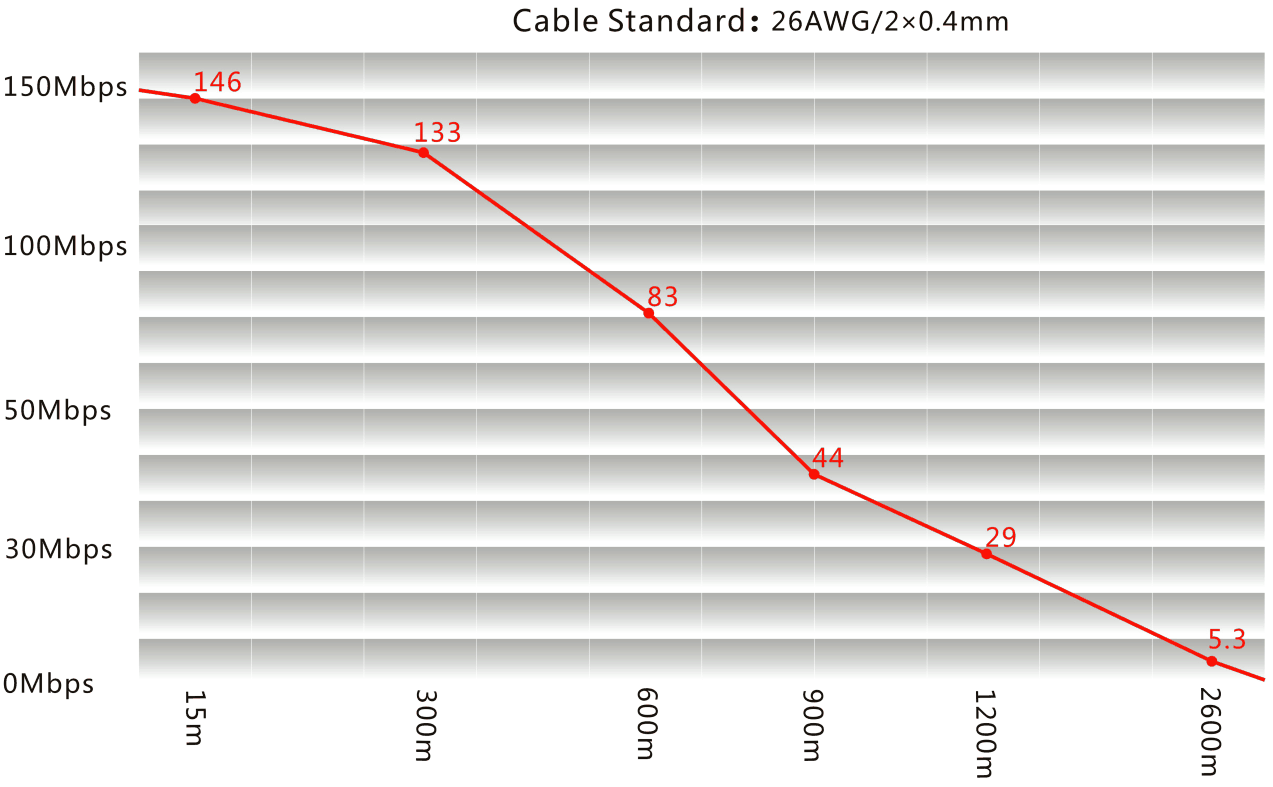
The above testing data is made under the condition of the cable not fully expanded. There may be differences compared with practical application of the data. Rate is only used as reference in project application.
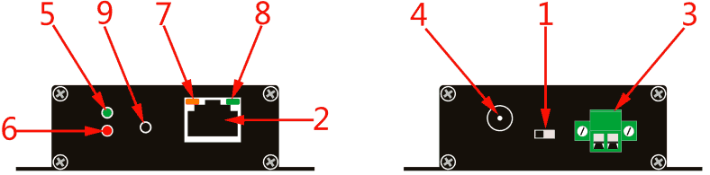
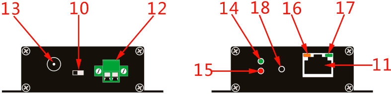
Installation Instructions:
|
Local (Master) |
Remote (Slave) |
||
|
Step |
Installation Instruction |
Step |
Installation Instruction |
|
1 |
Move the Master/Slave switch to master unit (1) |
10 |
Move the Master/Slave switch to slave unit (10) |
|
2 |
Connect the network cable to the RJ45 terminal of master unit (2) |
11 |
Connect the network cable to the RJ45 terminal of slave unit (11) |
|
3 |
2-wire terminal (3) |
12 |
2-wire terminal (12) |
|
4 |
Connect the power adaptor (12VDC) to the power terminal (4) |
13 |
Connect the power adaptor (12VDC) to the power terminal (13) |
|
5 |
Master/Slave indicator, it is normally on when device is master unit (5) |
14 |
Master/Slave indicator, it is always on when device is slave unit (14) |
|
6 |
Power indicator is normally on (6) |
15 |
Power indicator is normally on (15) |
|
7 |
Network data status indicator (7) |
16 |
Network data status indicator (16) |
|
8 |
Port link indicator is normally on after normal (8) |
17 |
Port link indicator is normally on after normal (17) |
|
9 |
Reset button (9) |
18 |
Reset button (18) |
Note: If the transmission distance is long, considering the wastage of the cable, please pay attention to choose better quality connectors.
Connection:
Use Tips:
When you use AN-LAN-EXT-HD-PIN, please follow the below tips as a reference, in order to reduce the fault in the process of using and the inspection work.
- Signal transmission cable must be the copper cable. Other material cables will cause the decrease of signal transmission quality and distance.
- Coaxial cable, twisted-pair cable, telephone line and power line can be all used to transmit network data signal in projects. A variety of cables arbitrary mixed connection also can reduce the quality of signal.
- Long-distance cable connections must be standard connection method, such as welding or using connectors.
- Please choose matching power supply (12VDC/1A).
- Set remote and local device by the switch. Remote and Local could be optionally installed. But it does not work if Local+Local or Remote+Remote
- There is no waterproof design for this product, please make sure it is used in dry environment.
- If device fails, do not disassemble or repair it by yourself. Please contact us timely.
In this video below, we are looking at interesting way to use these extenders in Point-to-Multipoint way using Copper Splitter in middle, and more on that – we demonstrate that using IP SIP phones as an end CPE devices here. So, what happens here is that signal get’s really “passively” split over 2 (and can be more) copper cables, and central device works as master side, while remote device – as slave side. Please note, that not all versions of these LAN extenders support such PMP mode, please talk to your account manager to see which model you need to order if you want make Point – to – Multipoint type connection!
Now, below here again, we have copper UTP cable, IPPBX and remote phone which we need extend far beyond 100m of traditional ethernet distance limitations. Just if in above video we used Point to Multimode, here’s more traditional Point to Point setup.
Of course, instead of IP Phones, you can have any other Ethernet IP device, such as IP camera, PC, Wifi Router, etc.
Description
AN-LAN-EXT-HD-PIN Ethernet Extender is a network signal extension device, which consists of remote unit and local unit. It can transmit network signal over 2-wire such as Cat5, telephone lines or coaxial cables, etc. The max distance can reach 3,000m and max bandwidth can reach 148Mbps. Meanwhile, it also can transmit telephone signal when transmitting network signal (adding an additional splitter).
So you can realize the network signal transmission over telephone lines. This device can be widely applied in network signal extending system, network security system, network information display system, network renovation and expansion systems, etc.