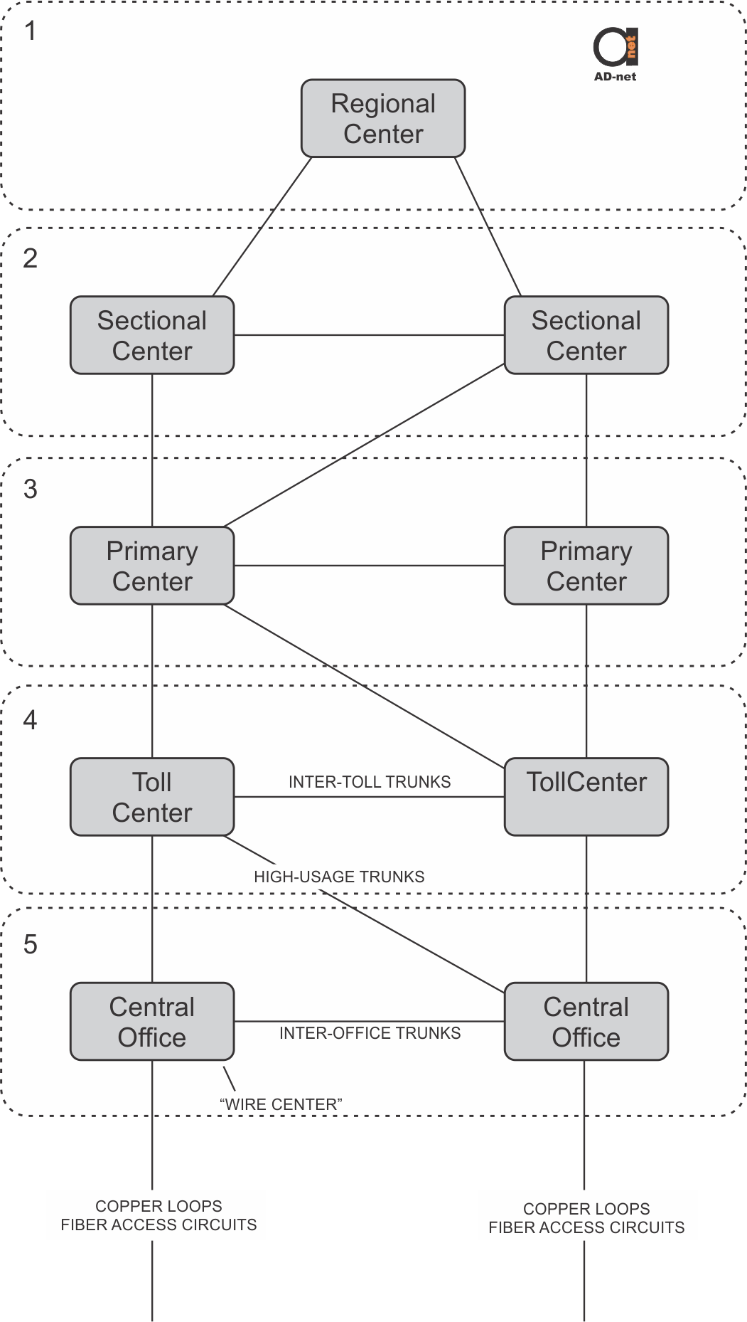
POTS and loops have already been discussed in great detail, and it’s time to look at PSTN’s trunk side. The Figure shown below illustrates Bell System switching centers’ five-level hierarchy.
Class 5: Central Office
At the bottom of the drawing, the End Office, End Serving Office, Serving Office, Class 5 Office, Number 5 Office or Central Office (CO) can be seen. These words all refer to the building, owned by the ILEC, where the switch it located. Telephone sets are connected to the switch with a loop or, if you’re connected to a remote switch, with a loop carrier system.

Figure 1: PSTN hierarchy
Wire Center
The CO is also called a wire center as this is the physical location where access wires are connected to the network core and switching network. Many cables containing numerous fibers and wires are routed to a cable vault situated in the basement of the CO. These are then taken up to a room in the center of the building via risers. Individual fibers and copper pairs from the street are then patched to individual fibers and copper pairs in horizontal in-building cables. These lead to the routers or muxes, switches, and their line cards or optical transceiver ports.
Most of the cables that leave the building are routed to customers. These cables contain fiber access circuits and copper subscriber loops.
Some cables leaving the building contain fibers that are connected to other COs, and fibers to the Toll Center for interconnection with Inter-Exchange Carriers. This is described in the sections below.
Local Calls
When a call is placed to your neighbor, their loop is normally connected into the same CO as yours is, resulting in the call being handled within the CO.
If a call is placed across town, the call is routed via trunk circuits to another CO switch and then onto the loop at the far end. As the CO is at level 5 in this hierarchy, CO switches are known as class 5 switches.
Class 4: Toll Center
Connecting the thousands of Central Offices together directly is not possible due to the huge number of connections that would be needed. To overcome this problem, a hierarchy was established.
The general idea is that metropolitan areas each have a building that is known as a toll center. Toll centers contain switches to which all CO switches in that city are connected.
If a phone call is made to another city, the call is routed from the closest CO to the city’s toll center, and from there to the far-end city’s toll center. From there it is connected to the far-end CO and then the far-end loop. This arrangement is often called a tandem arrangement, with the switches in toll centers called tandem switches or toll switches. The toll center is at level 4 in the hierarchy, so toll switches are known as class 4 switches.
Class 1, 2 and 3 Switching Centers
For example, as the Bell System is huge, the hierarchy contains more levels. States each have a primary center (class 3) and all the toll centers in the state are connected to it. The country is divided into seven sections, with all the primary centers in a section connected to the sectional center (class 2). Sectional centers are then connected to regional centers (class 1).
High Usage Trunks
Connections are installed between switching centers when the traffic volume warrants it. If there is high traffic between two COs that are not connected to the same Toll Center, a High Usage Trunk may be installed to connect those COs directly. This practice changes the actual implementation of the network from the hierarchical model shown to a meshed network that has many different routes between switching centers.
These trunk circuits have traditionally been used as reserved channels on SONET fiber-optic transmission systems organized in ring patterns around town, around the region and around the country.
In future, phone calls will be carried in IP packets in Ethernet frames on fiber optics when needed.


