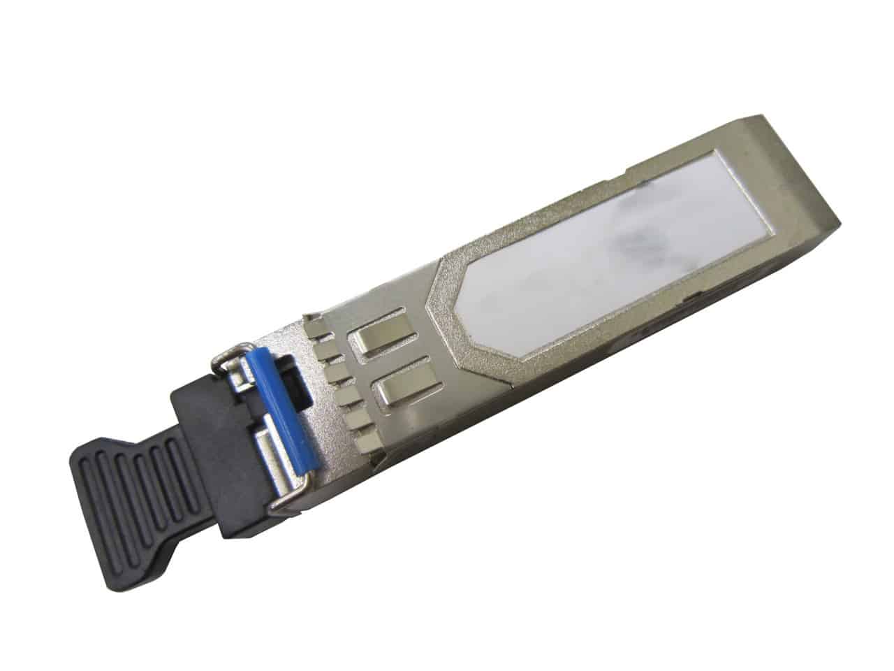
2.125 Gbps SFP Optical Transceiver, 10km Reach
2.125 Gbps SFP transceivers are high performance, cost effective modules supporting dual data-rate of 2.125Gbps and 10km transmission distance with SMF.
- Up to 2.125Gb/s bi-directional data link
- 1310nm FP laser and PIN photodetector for 10km transmission
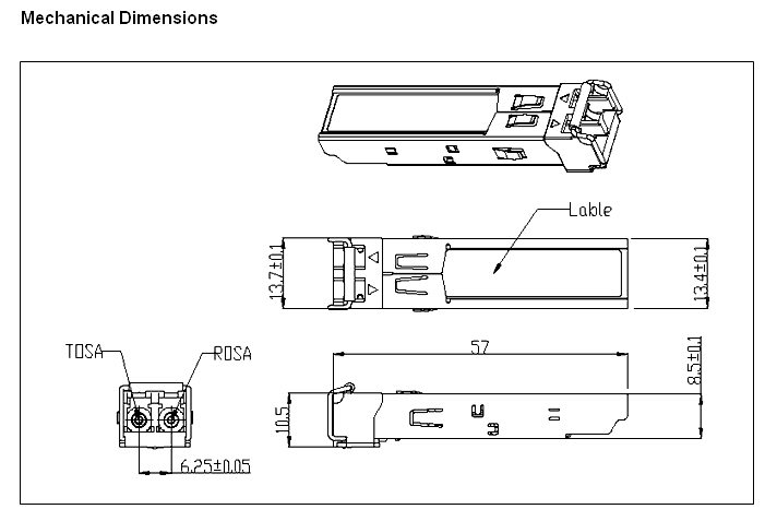
- Compliant with SFP MSA and SFF-8472 with duplex LC receptacle
- Digital Diagnostic Monitoring:
- Internal Calibration or External Calibration
- Compatible with RoHS
- +3.3V single power supply
- Operating case temperature:
- Standard : 0 to +70°C
- Industrial : -40 to +85°C
Table 1 – Absolute Maximum Ratings
|
Parameter |
Symbol |
Min |
Max |
Unit |
|
Supply Voltage |
Vcc |
-0.5 |
4.5 |
V |
|
Storage Temperature |
Ts |
-40 |
+85 |
°C |
|
Operating Humidity |
– |
5 |
85 |
% |
Recommended Operating Conditions
Table 2 – Recommended Operating Conditions
|
Parameter |
Symbol |
Min |
Typical |
Max |
Unit |
|
| Operating Case Temperature | Standard |
Tc |
0 |
+70 |
°C |
|
| Industrial |
-40 |
+85 |
°C |
|||
| Power Supply Voltage |
Vcc |
3.13 |
3.3 |
3.47 |
V |
|
| Power Supply Current |
Icc |
300 |
mA |
|||
| Data Rate |
2.125 |
Gbps |
||||
Optical and Electrical Characteristics
Table 3 – Optical and Electrical Characteristics
|
Parameter |
Symbol |
Min |
Typical |
Max |
Unit |
Notes |
||
|
Transmitter |
||||||||
| Centre Wavelength |
λc |
1260 |
1310 |
1360 |
nm |
|||
| Spectral Width (RMS) |
σ |
4 |
nm |
|||||
| Average Output Power |
Pout |
-10 |
-3 |
dBm |
1 |
|||
| Extinction Ratio |
ER |
9 |
dB |
|||||
| Optical Rise/Fall Time (20%~80%) |
tr/tf |
0.16 |
ns |
|||||
| Data Input Swing Differential |
VIN |
400 |
1800 |
mV |
2 |
|||
| Input Differential Impedance |
ZIN |
90 |
100 |
110 |
Ω |
|||
| TX Disable | Disable |
2.0 |
Vcc |
V |
||||
| Enable |
0 |
0.8 |
V |
|||||
| TX Fault | Fault |
2.0 |
Vcc |
V |
||||
| Normal |
0 |
0.8 |
V |
|||||
|
Receiver |
||||||||
| Centre Wavelength |
λc |
1260 |
1580 |
nm |
||||
| Receiver Sensitivity |
-18 |
dBm |
3 |
|||||
| Receiver Overload |
-3 |
dBm |
3 |
|||||
| LOS De-Assert |
LOSD |
-20 |
dBm |
|||||
| LOS Assert |
LOSA |
-30 |
dBm |
|||||
| LOS Hysteresis |
1 |
4 |
dB |
|||||
| Data Output Swing Differential |
Vout |
370 |
1800 |
mV |
4 |
|||
| LOS |
High |
2.0 |
Vcc |
V |
||||
|
Low |
0.8 |
V |
||||||
Notes:
1. The optical power is launched into SMF.
2. PECL input, internally AC-coupled and terminated.
3. Measured with a PRBS 27-1 test pattern @2125Mbps, BER ≤1×10-12.
4. Internally AC-coupled.
Timing and Electrical
Table 4 – Timing and Electrical
|
Parameter |
Symbol |
Min |
Typical |
Max |
Unit |
|
Tx Disable Negate Time |
t_on |
1 |
ms |
||
|
Tx Disable Assert Time |
t_off |
10 |
µs |
||
|
Time To Initialize, including Reset of Tx Fault |
t_init |
300 |
ms |
||
|
Tx Fault Assert Time |
t_fault |
100 |
µs |
||
|
Tx Disable To Reset |
t_reset |
10 |
µs |
||
|
LOS Assert Time |
t_loss_on |
100 |
µs |
||
|
LOS De-assert Time |
t_loss_off |
100 |
µs |
||
|
Serial ID Clock Rate |
f_serial_clock |
400 |
KHz |
||
|
MOD_DEF (0:2)-High |
VH |
2 |
Vcc |
V |
|
|
MOD_DEF (0:2)-Low |
VL |
0.8 |
V |
Diagnostics
Table 5 – Diagnostics Specification
|
Parameter |
Range |
Unit |
Accuracy |
Calibration |
| Temperature |
0 to +70 |
°C |
±3°C |
Internal / External |
|
-40 to +85 |
||||
| Voltage |
3.0 to 3.6 |
V |
±3% |
Internal / External |
| Bias Current |
0 to 100 |
mA |
±10% |
Internal / External |
| TX Power |
-10 to -3 |
dBm |
±3dB |
Internal / External |
| RX Power |
-23 to -3 |
dBm |
±3dB |
Internal / External |
Regulatory Compliance
AD-net SFP transceiver is designed to be Class I Laser safety compliant and is certified per the following standards
|
Feature |
Agency |
Standard |
Certificate / Comments |
| Laser Safety |
FDA |
CDRH 21 CFR 1040 annd Laser Notice No. 50 | 1120295-000 |
| Product Safety |
BST |
EN 60825-1:2007 |
EN 60825-2:2004
EN 60950-1:2006BT0905142001Environmental protection
SGS
RoHS Directive 2002/95/ECGZ0902007478/CHEMEMC
CCIC
EN 55022:2006+A1:2007
EN 55024:1998+A1:2001+A2:2003CTE09020023
| AN-2125-SFP-SM/1310/10 | 1310nm, 2.125Gbps, 10km, 0ºC ~ +70ºC |
|
| AN-2125-SFP-SM/1310/10D | 1310nm, 2.125Gbps, 10km, 0ºC ~ +70ºC, With Digital Diagnostic Monitoring |
|
| AN-2125-SFP-SM/1310/10I | 1310nm, 2.125Gbps, 10km, -40ºC ~ +85ºC |
|
| AN-2125-SFP-SM/1310/10DI | 1310nm, 2.125Gbps, 10km, -40ºC ~ +85ºC, With Digital Diagnostic Monitoring |
Description
The SFP transceivers are high performance, cost effective modules supporting dual data-rate of 2.125Gbps and 10km transmission distance with SMF.
The transceiver consists of three sections: a FP laser transmitter, a PIN photodiode integrated with a trans-impedance preamplifier (TIA) and MCU control unit. All modules satisfy class I laser safety requirements.The transceivers are compatible with SFP Multi-Source Agreement (MSA) and SFF-8472. For further information, please refer to SFP MSA.
Applications
2X Fiber Channel
Switch to Switch interface
Switched backplane applications
Router/Server interface
Other optical transmission systems