To understand the content of this article, you need to at least be familiar with the Ethernet protocol basics.
HINT: Check out all these articles about Ethernet Protocol to get solid intro on this topic.
We will cover the fundamental differences between normal Ethernet and the operation of EPON in this article.
In order to still support EPON as a part of the Ethernet standard, it was decided NOT to change any Ethernet specifications.
There are however a number of things that PONs must be able to do that are not required from other Ethernet systems. This challenge was resolved by adding a protocol layer in the lower region of the data link layer to merge the two.
EPON systems have multiple devices connected to one physical port at the OLT, and this could not be accommodated within Ethernet as it existed before PONs.
When cable TV companies became interested in managing EPON as if it were DOCSIS, the resolution of the problem was extended to DPoE. It is important for people who know Ethernet to understand which modifications need to be made for it to work in a PON.
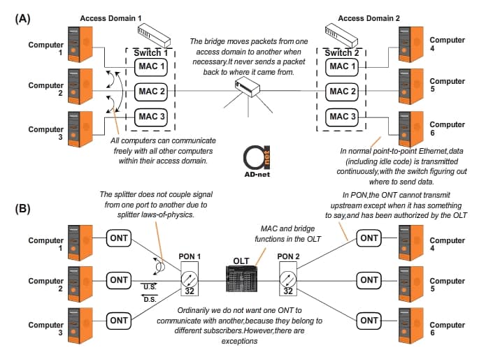
A diagram showing the problems is given in Fig 1.

Figure 1: PtP Ethernet vs PON
Shown at the top are three computers in each of two access domains connected in a conventional Ethernet system. A switch is used to connect computers within an access domain to allow any two computers in the domain to communicate with each other.
The switch is a point-to-point (PtP or P2P) device, with a direct connection to each computer. When it receives a packet from a computer containing the MAC destination address of another known computer in the domain, the switch sends the packet to that destination computer.
If a packet is received with an unknown MAC address, the switch sends the packet to all ports except the one from which it was received. If and when a response is received, the switch knows with which port the MAC address is associated and remembers this for future use.
In an Ethernet system with multiple P2P connections as shown in Fig 1A, data transmission in all directions is continuous, with short null messages being sent repetitively when no data needs to be communicated. This continuous transmission in each direction is needed to lock receive clocks so that they always stay ready to receive data packets.
As shown in the center of the drawing, in a typical enterprise network multiple access domains are interconnected by a bridge. There are a numerous reasons why not all computers in a network are in the same access domain.
Typically, each department uses its own access domain. This tends to speed up service, as there is not a single switch that could cause a bottleneck. Another scenario is when confidential information is exchanged within one department, e.g. financial or legal, and this information should not be available to other departments for security reasons.
A bridge operates the same as a switch, except that it can cater for multiple MAC addresses on a single port. In modern networks, the switch and bridge functions may be combined into a single piece of equipment.
Compare Fig 1A with Fig 1B, which shows the PON components corresponding to those in Fig 1A. Each PON is viewed as an access domain as they are all connected to the same OLT port, which combines the bridge and switch functions. There are a number of differences between an Ethernet system and a PON below it.
The communications between the ONTs and an OLT is vastly different to that of the P2P shown in Fig 1A.
The only connection between the multiple edge terminations (ONTs) and the single central termination (OLT) is passive optical fiber, which includes splitting. Downstream packets from OLT to ONTs are split and appear at the network interface of each ONT, which accepts only those intended for it. Upstream signals from the ONTs to the OLT ONLY appear at the OLT interface.
The upstream optical signal from one ONT does not appear at another ONT, except for signal leakage which is normally negligible.
Upstream communications from ONT to OLT can’t take place continuously. In the upstream direction, only one ONT may talk at a time. This is managed by the OLT and means that there must be both guard time between upstream transmissions, as well as synchronization time.
For downstream communication, each ONT on the PON receives not only the data intended for it, but all downstream data. The ONT must reject the data not intended for it. There may however be several data streams intended for one ONT in a downstream “pipe”.
Email may for example be delivered while a TV show is delivered over the Internet, and a voice call may taking place at the same time. Provision must be made for all these communications and more to occur simultaneously.
While computers in the access domain shown in Fig. 1A may communicate freely with each other, ONTs on the same PON may often not be allowed to communicate directly with each other, as the ONTs are often not part of the same enterprise, but are owned by independent subscribers. These subscribers would definitely not want strangers to have access to their network.
With IPTV, the same program packet should go to more than one ONT if it is being watched simultaneously in multiple homes. This is known as multicasting, which is key to distributing video on a data network efficiently.
In order to accommodate the various requirements mentioned, which are different from normal Ethernet operations, the 802.3ah Working Group responsible for developing the original EPON standard had to add these to the Ethernet standard in such a way that it didn’t require any Ethernet components to act differently than what they did previously.
This was done by adding LLIDs between the physical layer (in our case, an optical transport layer), and the layer where Ethernet performed its many useful functions.
Hint: In this article you can find introduction to OSI Layer 1 (physical layer)
After “conventional Ethernet” has determined that a packet is ready for transmission, the LLID “takes over” and adjusts the packet for the PON medium.
On the receiving side, the physical transport delivers the packet to the LLID to be converted into something that normal Ethernet can understand. This is done without adding any extra bits to packets, as an Ethernet packets includes 16 bits for clock synchronization not needed in modern P2P Ethernet systems.
These spare bits were left over from the days of half duplex transmission and were pressed into service as the LLID header. They are then converted back into the original run-in sequence before the packet is presented to the Ethernet MAC.


