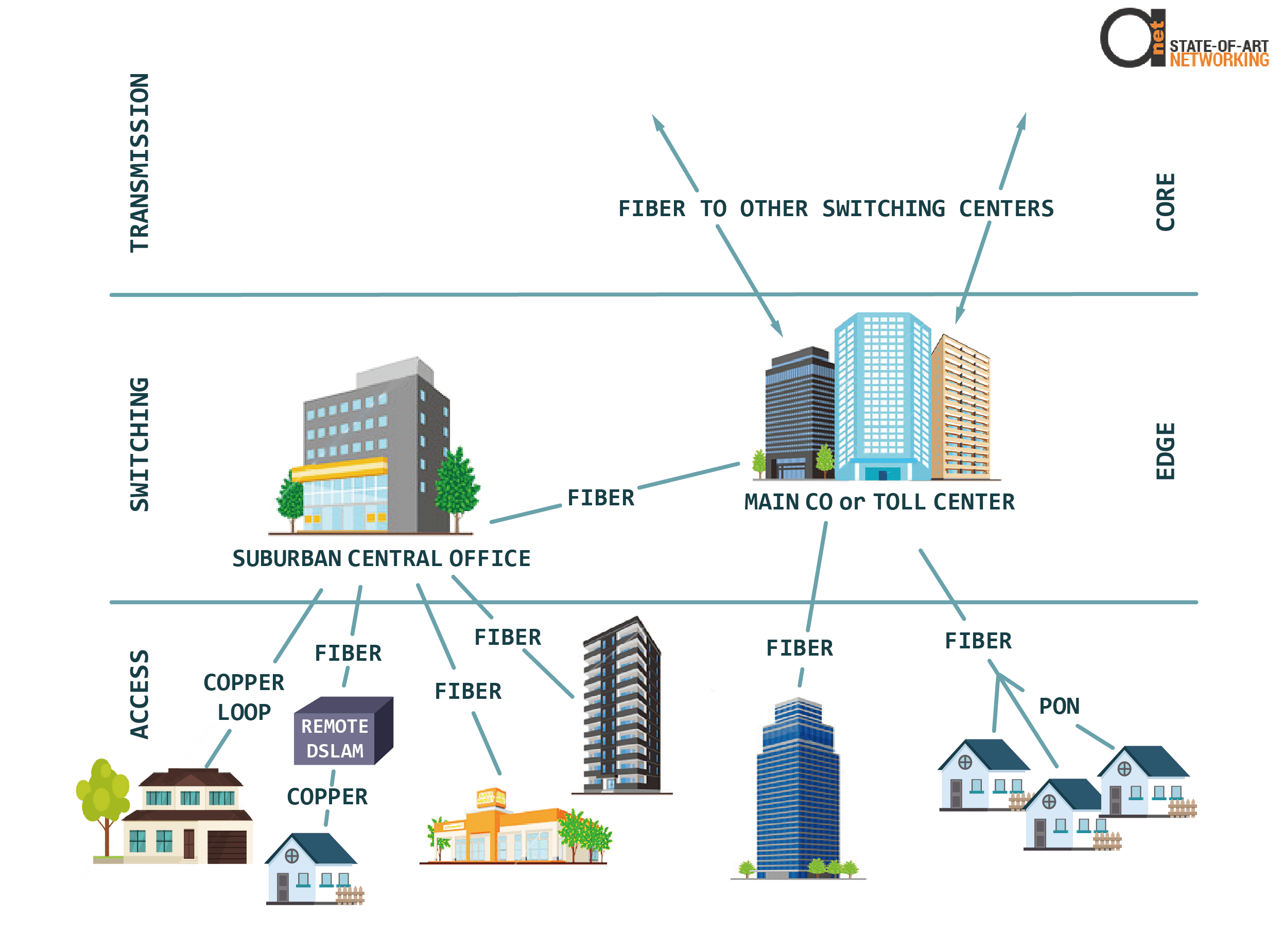
Telephone networks are traditionally described as consisting of three parts: access, switching and transmission, also known as the access network, switching network and transmission network.

Figure 1: Structure of Telephone Network
Access Network
The access network, also known as the outside plant, is the cabling and equipment that is used to connect the switching network to the customer, typically at a Central Office (CO).
Although it is also known as the “last mile”, the people who work in this part of the industry call it the “first mile”. The word mile in this context is simply a word and the actual distance may be much longer or shorter than a mile.
The last mile was historically implemented by using twisted-pair copper wires in feeder cables. These typically contained a thousand or more pairs leading from the CO to wiring connection points in neighborhoods known as Serving Area Concept (SAC) boxes or Outside Plant Interfaces (OPIs).
From these points, distribution cables with a hundred or more pairs run down streets. Terminals are then used to connect these to the customer premise with a drop Wire. Physical connections are used in the terminal and OPI/ SAC box to connect the CO to the customer premise. Since electrical current on these two wires flows in a loop, the pair is called a loop.
More information about PSTN, and CO, CPE, loop and trunks you can read in this article.
Where this infrastructure is installed in neighborhoods, these are referred to as brownfields. Fiber to the Neighborhood (FTTN), followed by DSL to the subscriber is used to implement high-speed internet access to the large existing base.
Fiber is pulled from the CO to each OPI/ SAC box, which is generically known as an outside plant enclosure.
The fiber is connected to a DSLAM inside the enclosure, which houses banks of DSL modems. Short pairs of wires are used to connect the DSLAM’s modems to each subscriber for high-speed Internet.
The customer’s network access is provided by fiber to the enclosure connected to a short run of copper to the customer’s premises.
The shorter the copper run at the end, the faster the speed. VDSL2 technology achieves 200 Mb/s with a run length of maximum 150 yards (150 meters).
New neighborhoods are called greenfields and fiber to the premise (FTTP) is used in this case. A Passive Optical Network (PON) strategy is often employed for residences and small businesses and 32 customers typically use time sharing to share a fiber backhaul. Medium and large businesses are usually connected by using a dedicated fiber.
Switching Network
The switching part of the network traditionally employed a five- level hierarchy, with the Central Office situated at the lowest level of the switching center hierarchy.
A Central Office is the point where all the access wires meet and are connected to switching equipment. Although this equipment is often owned by the telephone company, it might be owned by a competitor collocated in the CO.
Previously, the switching equipment was a circuit switch that established connectivity to an outgoing circuit for the phone call’s duration. Nowadays, this switching equipment is a router or packet switch that forwards one packet at a time.
Network engineers call this equipment edge equipment, as it is situated at the edge of the telephone company’s core network. Edge equipment provides data concentration and converts between the physical media of the access network and the physical media of the connections between switching centers and the transmission network.
A toll center is used to connect the COs in a city. This building is located at the second level in the switching hierarchy and is the interconnection point with transmission networks. The networks could be owned by the same telephone company, or by a competitor.
Transmission Network
The transmission network connects switching centers to provide high-availability, high-capacity connectivity between COs and between cities. Transmission engineers call this part of the network the network core by. Previously, the capacity was organized into fixed 64 kb/s channels and routers or switches directed traffic onto the channels. Nowadays, traffic on the core is all packets that are transmitted on demand.


