The process of development and deployment of FTTP network requires high attention to equipment installed in central office. Designer should specify where to install WDM coupler making minimum connection interfaces. The main factor in cable layout design is choosing connection routes between the termination point of the feeder cable and the transmission equipment.
Figure 1 is showing simplified diagram that is demonstrating equipment that may be connected to an optical cable network. Equipment includes:
- OLT interfaces (such as telephone switches)
- ATM switches
- OC-N or STM-N transmission systems
- Ethernet modules
- Digital video equipment
OLT rack is combining all the incoming signals to one 1490 nm wavelength flow and is sending this stream continuously to the optical multiplexer. Analog video signal is carried out by 1550 nm wavelength and is combined into the the same downstream flow as the 1490 nm voice and data stream.
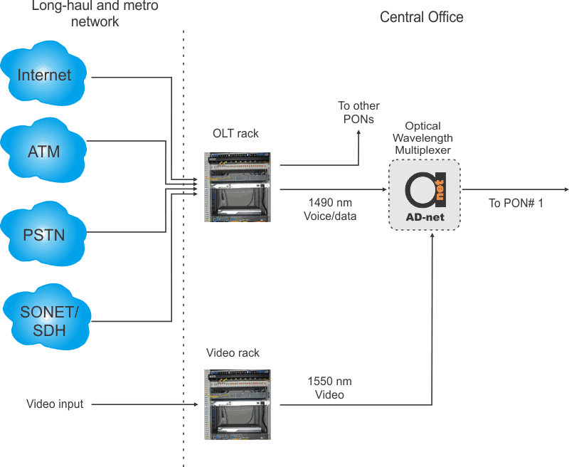
Figure 1. Simplified diagram of the transmission equipment in a central office.
OLT is usually installed in in 2m equipment rack. This rack may include video equipment as well, but usually it is installed in different nearby rack.
Main equipment in central office cabling network are:
- Video rack(s)
- OLT rack(s)
- Fiber distribution frame(s)
- Fiber entrance cabinet(s)
- Multiple types of different indoor optical fiber cables
The FDF (fiber distribution frame) is a rack size structure allowing interconnection of equipment easier and more flexible using short fibers. This large panel allows to change configuration easily as the central office is expanding.
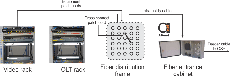
Usually there is a fiber entrance cabinet where all the cables coming from OSP are terminated. This equipment may be placed on the wall or installed on the equipment rack. OSP cable may contain hundreds of fibers, making entrance cabinet well designed equipment for easy identification and splicing of cables.
WDM coupler is used for combining and separation of 1310-, 1490-, and 1550-nm wavelength signals onto and off a single optical fiber. As mentioned above, OLT and video transmitters are normally installed on the different racks. In this case, WDM coupler is usually installed on OLT rack or together with FDF.
In the case of installation together with OLT, three cables are required. First two for connecting to WDM inputs (OLT and video) and last one for connecting the output of WDM to FDF. In case when WDM coupler is installed to the back of FDF, there is one less cable required, because the WDM resides in the FDF. It may result in some complexities, if the OLT rack needed to be moved , repaired or replaced, all the video connections to the WDM should be changed.
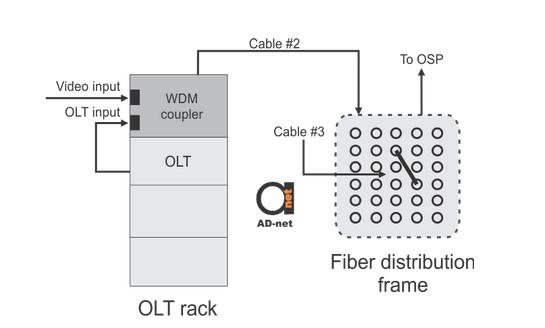
Figure 3. Cable connections in the CO if the WDM coupler is in the OLT equipment rack.
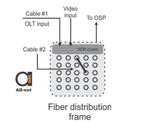
Figure 4. Cable connections in the CO if the WDM coupler resides in the back panel of the FDF.
The OLT and video rack photo what is used above, in fact are from real installation of our OLT in Cambodia. You can see it bigger in this Google+ post.

