Shielded Twisted-Pair (STP)
IBM first made shielded twisted-pair (STP) cabling popular when they introduced data cabling type classifications. Although STP costs more than UTP and is also more expensive to install, STP has some definite advantages over UTP.
Although the ANSI / TIA-568-C standard for cabling identifies IBM Type 1A horizontal cable supporting frequencies of up to 300MHz, it is not recommended for new installations. It is not as susceptible to electromagnetic interference (EMI) as is UTP cabling, simply because each pair within the cable is properly shielded.
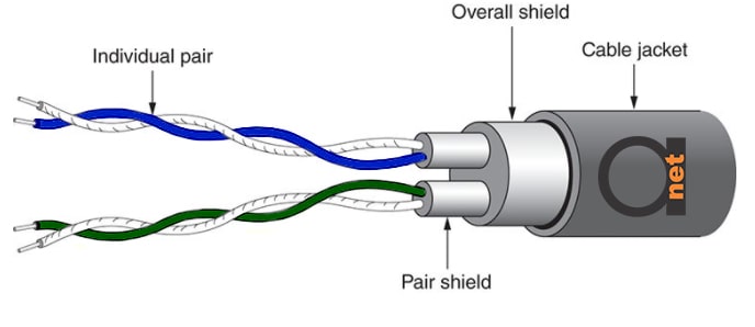
Various STP cable types, such as types 1 and 1A cable from IBM, use a plaited copper shield. This arrangement protects significantly against EMI. STP cabling has pairs of twisted wire (normally two) that are wrapped in a shield of foil inside the woven copper braided shield. Other STP cables only have the shield around the pairs of wires and not the braided shield.

Figure 1: Typical STP – Shielded Twisted Cable
The IBM scheme uses 22 AWG wire in STP cables. This is slightly bigger than the 24 AWG wires typical used by UTP cables. Although the nominal impedance is typically 150 ohms, different category versions may use a 100 ohm nominal impedance.
STP are nowadays typically made in 24 AWG, which is identical to the size of the copper conductors in UTP cables.
Merely using STP cabling will not guarantee that the cable’s resistance to EMI will improve, or that emissions generated by the cable will be reduced. Several conditions have to be met in order to maximize the performance of the shield:
- Electrical continuity of the shield must be maintained along the entire link.
- Every link components should be shielded, i.e. UTP patch cables may not be utilized.
- The pair must be fully enclose by the shield and the core must be fully enclose by the overall shield. If there is an opening in the shield covering, it will allow EMI leakage to get through.
- The shield should be earthed at both sides of the link. The building grounding must follow grounding standards, e.g. J -STD-607-A.
If a single one of these conditions is not met, the shield’s performance will be degraded badly. Tests for example show that if the shield is not continuous, a shielded cabling system emissions increase on average by 20 dB.


