EPON architecture uses the standard PON technology, when single feeder line going to the splitter. Splitter is connected up to 32 distribution branches. IEEE 802.3ah EFM standard specifies conditions for distance, which maximum is 10 or 20 km between the OLT and an ONT. Transmission distance is depending on the splitter and optics class selected (class B or class C). EPON implementation allows to use cheaper and more reliable components, because it is using Ethernet MAC (media access control) and PHY (physical layer) chip sets.EPON uses 1490-nm wavelength for downstream (OLT to ONT/ONU) and 1310-nm wavelength for upstream (ONT/ONU to OLT). At the same time 1550-nm wavelength is free and is commonly used for other services, such as multichannel video transmission from OLT to customers. EPON architecture is based on standard gigabit Ethernet protocol, with nominal bit rate of 1250 Mbps, which is sent using 8B10B encoding. 8B10B is adding two extra bits to every 8-bit package for timing correction and debugging. In addition to the 8-bit data characters, there are special 10-bit control characters, which are commonly used for indication whether the information bits are for idle data, test messages, or frame delineation.
OLT in EPON acts as the network controller, which communicates with ONTs (ONU), which prevents direct interactions ONTs on the same EPON. The key features of OLT are:
- Discovery process, which is continuously determining if any ONT’s (ONU) have left or joined network.
- Registration of the newly joined ONTs.
- Assigning of the varying amounts of upstream transmission bandwidth to each ONT (ONU).
- Ranging process, which is calculating transmission time delay between an OLT and each ONT (ONU).
- Time-stamped message generator, for global time reference purposes.
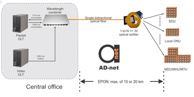
Figure.1 Basic EPON architecture and operational control.
Standard Ethernet frames are used for EPON data transmission. The length of the standard Ethernet MAC frame can vary in length from 72 to 1526 bytes.
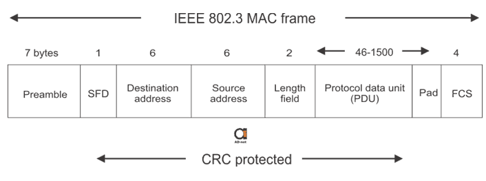
Figure 2. Format of a standard Ethernet frame.
Frame is divided into eight frames which has different functions:
Preamble. It is using repetition of seven 8-bit patterns (10101010), which alerts the receiving system that the frame is coming. It is a square wave pattern and it is synchronising receivers timing to the beginning of the frame.
- SFD (Start Frame Delimiter). It is 1 byte sequence (10101011), two consecutive ones are used for indicating the first bit of first frame of the frame.
- DA (Destination Address). Next destination of the packet is stored in this 6-byte field. The first bit specify, does it need to be sent to a single user or to a group of stations. Second bit distinguishes between a local or global address.
- SA (Source Address). 6 bytes of SA field are storing physical address of the last device that forwarded the frame.
- Length and Type of PDU (Protocol Data Unit). Used for indicating the length of the PDU (the data field), which can be up to 1520 bytes long.
- PDU (Protocol data Unit). This field contains information field and LLC (Logical Link Control) data. LLC is used for enabling data exchange between end users.
- Pad. This field is used for ensuring that the frame sie is always at least 64 bytes long. This is necessary for successful collision-detection operation.
- FCS (Frame Check Sequence). In FCS field 32-bit CRC (Cyclic Redundancy Check) is used for error check in the frame. To perform a binary division calculation, CRC uses the bits in the DA, SA, length and PDU fields. Result of this calculations is added to a frame and is recalculated at the destination. If the results are different, an error has accrued and the frame is rejected.
In an EPON the network is full-duplex operational, so preamble is not used. IN EPON frame the 8-bytes of preamble and SFD are replaced by the following EPON-related fields (which are also 8 bytes):
- SPD (Start-of-Packet Delimiter) – is a 1-byte field containing clocking information and used for synchronisation of the ONTs with OLT.
- Next three bytes are reserved for future use.
- LLID (Logical Link IDentifier) – 2-byte tag.
- FCS (Frame Check Sequence) – 2-byte field containing error detection information for the EPON frame.
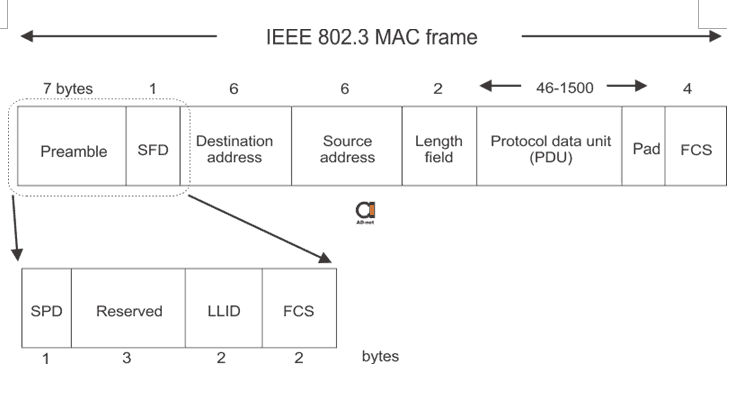
Figure 3. Epon frame format.
Ethernet frames are broadcasted by OLT to the ONTs, in the downstream direction. ONTs are filtering the frames using the LLID tag, so ONT will reject frames intended for other ONTs. When the data is send back, ONT places its own LLID in the frame.
If traffic is coming upstream from many different ONTs it could cause packet collisions. The MPCP (MultiPoint Control Protocol) procedure is used to avoid packet collision, and is arbitrating the channel access between the central office and the EPON subscribers.
Packets arriving to the OLT are having bursty nature which results in large optical power level and phase variations. This is happening because packets are coming from many ONTs which are allocated at different distance. Optical receivers are designed for managing optical signals with constant amplitude. So it is necessary to use burst-mode receivers which are used for adapting to the variation in optical power and phase alignment.

