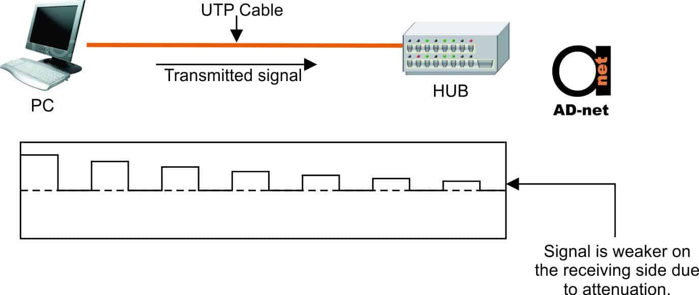
Loss of signal is called attenuation.
Attenuation occurs when signals travels through cables, but not all of the signal reaches the other end of the cable. Signal loss increases with the length of a cable. With cables that are too long, the signal loss will in fact be so big that the data will no longer be transmitted properly.
In the ISO/IEC 11801 Ed. 2.2 and TIA/BIA 568-C cabling standards, attenuation is often referred to as insertion loss.

Figure 1: Attenuation schematic example
Attenuation is measured at the receiving end of the conductor and is measured in decibels (dB). If for example 11 dB of signal is inserted on the transmission end, and 3 dB of signal is measured at the receiving end, the attenuation would be calculated as 3 – 11 = —8 dB.
The negative sign is usually not mentioned, so the attenuation is given as 8 dB of signal loss. If 15 dB is inserted at the transmitter and 10 dB measured at the receiver, then the attenuation would be 5 dB signal loss. As a lower attenuation value indicates that more of the original signal is received, the lower the number, the better.
A cable’s attenuation will increase with an increase in frequency. A 100 meter cable’s attenuation would typically be less than 2dB at 1 MHz, but it would be more than 20dB at 100 MHz!
An increase in temperatures also increases the effect of attenuation. For each degree Celsius increase in temperature, attenuation typically increases by 1.5% for Category 3 cables and 0.4% for Category 5e cables. The attenuation value also increases by 2% to 3% when cable is installed in metal conduit.
Attenuation values for cables are very important because the signal must still be recognizable when it arrives at the receiver.
Insertion loss values vary depending on the category of the cable and the frequencies used. As the bandwidth of the cable increases, the allowed attenuation decreases (less loss is allowed), although the difference between Category 5e and 6 is negligible at the common frequency of 100MHz.
This article discusses Maximum Operating Frequency for various Cat copper cables.
Cable characteristics that contribute to insertion loss are discussed below:
Mutual capacitance
This characteristic is an electrical phenomena that occurs when a cable has more than one conductor and these conductors are placed close together. The insulation material will absorb and store a small amount of the signal energy, acting as a capacitor between two or more conductors in a cable. The dielectric constant, a property of the insulating material, has a big influence on the mutual capacitance. Dielectric constants are different for different materials. A material with a lower dielectric constant will cause less signal loss.
HDPE and FEP both have low dielectric constants that, along with other properties, make them ideally suited for use in high-frequency cables.
Resistance of the Conductor
The resistance of the conductor acts as a barrier to signals as it restricts electricity flow through the cable conductors. Although this causes some of the signal’s energy to be converted to heat, LAN cabling generates negligible heat as it uses very low levels of voltage and current. Longer cables and smaller conductor diameters (actually, cross-sectional areas) create a higher resistance. Resistance is more or less a fixed property of the conductor material after allowing for dimensional factors. Copper, silver and gold are often used as conductors as these materials have a low resistance.
Impedance
Impedance is a combination of resistance, inductance and capacitance, and is expressed in ohms. The impedance of a typical UTP cable is between 85 and 115 ohms. All UTP Category 3, 5e, 6, and 6A cables used in the United States are rated at 100 ± 15 ohms. The impedance value is a useful property to measure when testing cables for shorts, problems, and mismatches. A cable tester could measure three possible impedance values that indicate a problem:
- An infinite impedance reading indicates that the cable is open or has been cut.
- Impedance readings that are not between 85 and 115 ohms indicate a mismatch in the type of components or cables. This might for example mean that an incorrect cable type has been cross-connected into the circuit, or that the wrong type of connector has been installed.
- An impedance reading of 0 indicates that there is a short circuit in the cable.
When some electrons flowing through a cable hit an impedance mismatch, or imperfection in the wire, they will be reflected back to the sender. This is known as return loss. Impedance mismatches often happen at locations with connectors, but they can also happen in cable where a variation in the characteristic impedance along the length of a cable is present.
When electrons travel a big distance before being bounced back to the sender, the return loss may not be noticeable, as the returning signal may have dissipated due to attenuation before it reaches the sender. If the signal’s echo from the bounced signal is strong enough, it can interfere with ultra-high-speed technologies, such as 1000 Base-T.


