Noise can be defined as Signal Interference.
All electrical activity in a cable that isn’t the signal itself is noise and threatens the integrity of the signal.
There are many sources of noise, both from within and outside the cable. Connector designers spent a major amount of effort and time in controlling noise, as uncontrolled noise can easily overwhelm the data signal and prevent a network from operating.
Twisted-pair cables use balanced signal transmissions. The signal traveling in one conductor of a pair essentially has the same path as the signal traveling in the opposite direction in the other conductor.
This is different in a coaxial cable where the center conductor provides an easy route for the signal, but the foil and braid shield making up the other conductor are less efficient and present a more difficult route for the signal.
An electrical field is created when signals travel along a pair. If the two conductors are perfectly symmetrical, the signal travels smoothly. The thickness of the insulating layer, miniscule changes in the diameter of the copper, or the centering of conductors within the insulation however all cause disturbances in the electrical field. These disturbances are called unbalances and electrical unbalance causes noise.
When the dimensions of the two conductors of the pair are not identical, the result is resistance unbalance. Resistance unbalance can be due to poorly manufactured conductors, mismatched conductors, or one conductor being stretched during installation.
Capacitance unbalance is caused by the dimensions of the insulation surrounding the conductor. If the insulation is thinner on one conductor than on the other, or if the manufacturing process is not properly controlled and the conductor is not perfectly centered in the insulation, the result is capacitance unbalance.
Both these sources of noise are usually controlled by the manufacturer and are relatively minor when compared to crosstalk.
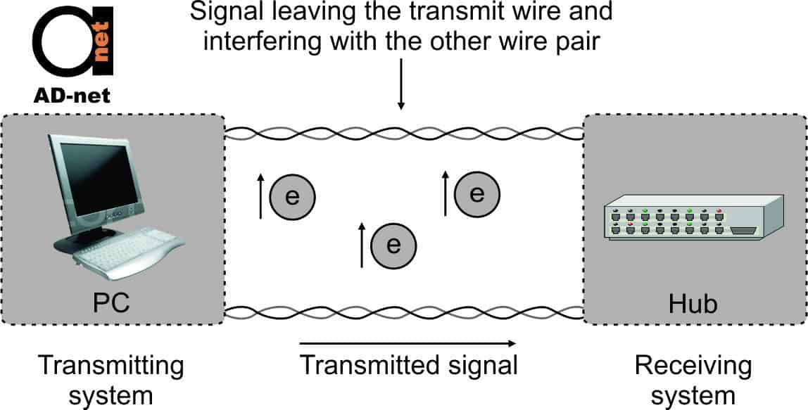
When you hear another conversation over yours on a telephone, that’s an example of crosstalk. Crosstalk happens when a part of the signal that is transmitted on one pair, leaks over to another pair.
An electrical field is created when a pair is used. This field induces voltage in adjacent pairs, resulting in part of the signal also being transferred. This phenomenon worsens when conductors are parallel and crosstalk is more likely to happen at higher frequencies.
When the two conductors of a pair are twisted around each other, the energy is coupled out of phase and the electrical field is canceled. This results in a reduction of the signal transfer.
The twists must be however be symmetrical, i.e. the conductors must be twisted around each other and one must not be wrapped around another that’s straight. Two adjacent pairs should also never have the same twist interval.
This is because those twist points could become convenient signal-transfer points. Generally, shorter twist intervals produces better cancellation and reduces crosstalk. That’s the reason why Category 5e and higher cables are characterized by twist intervals that are very short.
Crosstalk is measured in decibels, with a higher crosstalk value signifying less crosstalk noise in cabling.
It might seem illogical to say that higher crosstalk values are better.

Figure 1: Crosstalk
With attenuation, output signals are measure at the receiving end of one pair, while crosstalk coupling is measured between two separate pairs. The testing is done by measuring how much signal energy did not transfer to another pair.
A pair (or in the case of power-sum measurements, pairs) is energized by a signal. This pair is the disturber.
Measurements are done on another pair that is called the disturbed pair. When what is inserted on the disturber is subtracting from what is measured on the disturbed pair, this indicates how much signal stayed with the disturber.
If an 11 dB signal is for example placed on the disturber, but 5 dB is detected on the disturbed pair, -6 dB of signal did not transfer (5 – 11).
The minus sign is ignored, so the crosstalk is recorded as 6 dB. If only 4 dB were measured on the disturbed pair, then 4 – 11 = -7 dB of signal did not transfer, and the crosstalk value is recorded as 7 dB. A higher crosstalk number represents less loss to adjacent pairs.


