In the beginning of telecommunication era it was common for cable to be terminated directly at component inside workstation or equipment closet. Nowadays this approach cannot be taken – it is against one of the main rules of structured cabling. Ends of the cables should have connectors providing access and transition for attachment to system electronics.
Connectors might be “male”, “female”, or “hermaphroditic”. Also they could be symmetrically shaped (could be input any way user wants – most common example is 3.5mm audio jack) or might have some asymmetrical pins ensuring it can be connected only one way (example RJ-45).
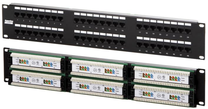
110-style termination blocks are the most common ways of terminating UTP and ScTP cables. This patch panel contains rows of specially designed punch-down slots where cables would be terminated. In order to terminate cable it does not need to be stripped of insulation. The metallic parts of the terminating block would pierce insulation and would establish connection.

Figure 1. Punch down block
Both UTP and ScTP might have either solid copper conductor or several tiny strands of copper. Solid conductor offers better electrical superiority, however they are damaged when often flexed. Stranded cables are more flexible, but have higher attenuation and cross-section geometry changes could result in electrical anomalies. Therefore solid conductor cables are commonly used for horizontal and backbone cabling where there is no further cable movement expected. The type of the conductor directly affects the plugs, patch panels, and connectors it could be used with.

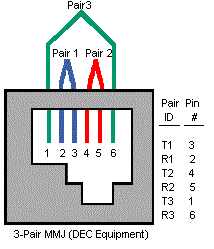
Figure 2. The DEC MMJ jack
Because of the nature of IDC (Insulator Displacement Connector), which punctures the cable, it is required to use stranded cable. Solid-core conductor is too fragile for this kind of cable and could be cut-off completely when punched in. In worst scenario, it would create temperature dependent connection, which will work in hot temperatures when copper expands, and would fail to work when temperature conditions are cold.
Table 1. Common modular-jack designations and their configuration.

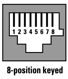
Modular connectors so commonly used in telecommunications world are coming in four-, six-, and eight-position configurations. One should be careful, some connectors made for specific purpose might not have all metal contacts in place. In case the ScTP cable used, the connector and jack should have metal shielding in place that is connected correctly in order for shield to be functional. Most common cable is RJ-45 with 8-position connector and 8 contacts. Other variations are visible from Table 1. Some big corporations design their own standards for connectors and jacks. Example – MMJ designed by DEC. In order to ensure that other 6-pin cables would not fit this jack, it is using displaced clip position as shown in Figure 2. Another example of personalized solution is shown in Figure 3. Note the key slot that ensures there would be no confusion with traditional 8-pin cable.

Figure 3. 8 position keyed modular jack


