This article is a next logical in a series of our Networking 101 article series, and we still continue discuss OSI Layers – without this, you can’t really get into more complicate topics.
If you did not read yet, check out previous articles in this series:
In networking, there are different ways you can connect or network equipment. One of the most popular methods is Ethernet, in Layer 1.
Ethernet is an IEEE standard including cable types like Cat5, Cat6, as well as single mode fiber and multi mode fiber.
Some common ethernet cables you’ll encounter in the network world include orange and aqua multimode, fiber optic cables, yellow single mode, fiber optic and cat5 and cat6 cables.
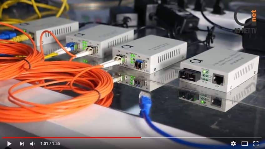
Figure 1: Orange color fiber cable is Multimode Type, and Yellow one is Single mode, while blue type is Cat5e copper cable.
If you are interested to check out what’s happening in above image, then this is pretty interesting test setup we made using our SFP-SFP converters and Gigabit Media converters, to show, how you can convert single mode to multimode type not changing a cables that are already installed. Check the video out below, it’s really worth to see:
Video 1: Sending single mode devices over Multimode cables.
Multimode cabling would typically be used for short distance, high bandwidth connections, single mode fiber optic cabling is used for long distance, high bandwidth connections.
Single mode fiber has the ability to connect and network devices that are miles apart, so if you had to connect buildings, then you would probably be using single mode.
While multimode would be used for connecting devices within the same room or maybe between floors.
Interesting read by the way: Can I use Single Mode Patchcord instead of Multimode and vice versa?
Due to distance and bandwidth, limitations compared to fiber or copper cabling is going to be used for shorter lower bandwidth connections for devices like computers, phones, and printers. Now let’s take a look at how these cable types could be used for connectivity within a network topology.
Yellow single-mode cable could be used for high bandwidth, long distance connections like between buildings than we would have our multi-mode cable for high bandwidth connections for inter closet or inter floor, shorter distance switch connections, and then of course our Cat5 and Cat6 copper cables would be used for end hosts to connect to access layer switches. See below diagram for more clear understanding of this concept.

Figure 2: Single Mode Fiber is interconnecting 2 buildings, while copper cables are and multimode cables are used within the building.
Now, for network devices to communicate over copper cabling, traffic is transmitted and received over specific pins. Certain devices will always use common pins for both directions. For example, PC’s will use pins one and two to transmit data and three and six to receive data.

Figure 3: Transmit & Receive Pins between 2 PC’s
This is important to understand to know which type of cables to use between our network devices. One type of copper cable is a straight through cable. If you looked inside of a straight through cable, you’ll find multiple pairs of smaller wires. These wires are terminated at each end in a certain order. A straight through cable has the same pairs and each end, hence the name straight. This type of cable can be an issue, one connecting a like devices that transmit on the same pins.

Figure 4: Straight through cable
For example, if we connect the two PC’S, via straight through cable, the transmit and receive directions would be the same making communication fail. In this scenario, we would want to use a crossover cable. Crossover cables are typically red and they have certain pairs terminated on opposite sides to flip flop the transmitted pins. This way, even though devices are using the same pins on each side, the cable crosses the transmit to the receive in both directions.

Figure 5: Crossover cable
The same problem exists on network switches and we would need a crossover cable to connect the two switches together. Now if a non-like devices are connected, then we can use a straight through cable without any issues because they would transmit and receive on opposite pins.
By design, switches actually purposely transmit and receive on pins that are the opposite of edge devices that would typically be connected to switches. Since these devices are meant to connect two ethernet switches, it makes sense that they would by default already transmit and receive on different pins so that a straight through cable could be used.
")
Figure 6: Connecting non-like devices, like PC to switch (very common scenario)
OK, now that you understand when to use a straight through and crossover cable, you can forget about it. Well not entirely, but there is a feature called Auto MDIX that can actually dynamically switch and data to transmit and receive on the correct pins regardless of the cable termination so you can connect. I like devices like switches with a straight through cable.
Auto MDIX is actually on by default on most devices nowadays, but you may occasionally run into situations where you need to use a crossover cable and in fact they tip for packet tracer. If you connect it to switches or routers together, you will need a crossover cable or the links will never come up.
So far we’ve been talking about copper cable connections. Well, we also have a similar problem when we use fiber optic cable in between our network devices. When we connect our switches, we’re going to have fiber jumpers that have two strands, a transmit and receive.
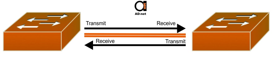
Figure 7: Using Fiber Patch cables (or jumpers).
If we have a factory made cable and we connect the two switches, then we would have no problem because the strands would be terminated to be the opposite for the transmit and the receive, but when we’re connecting through long fiber plants within buildings, sometimes the fiber or terminations can get flipped flopped throughout the topology and we can guarantee you if you have a networking job or getting networking job and you have to connect devices with fiber jumpers, you’re going to have to flip flop your fiber strands at one point to bring up a link between switches.
Also note, that fiber jumpers, unlike copper cables, where it’s all RJ-45 UTP connectors are used, then for fiber, you can get even 16 (!) different connectors!
So just remember when you’re using fiber jumpers between devices, and if your ports are enabled and nothing is coming up, then your best bet is to break open the fiber connector and flip flop the jumpers.
All of these different cable types that we’ve covered, can we use for different IEEE Ethernet standards. Different speeds are supported over our different ethernet types depending on the physical characteristics of the cable.

Figure 8: This chart shows the commonly used base names from 10 megabits per second all the way up to 10G, 40G per second and beyond.
So for example, if you wanted to connect two switches together with fiber optics at one gigabit per second, then you would make sure that you were using 1000Base LX or SX compatible equipment and the same would go for copper. Or if you had to connect all of your copper and hosts like computers and access points and phones at one gigabit per second, then you’d want to make sure that your cabling could support 1000Base-T connections.

