The fusing of fibers together by an electric arc is known as FUSION SPLICING. It is the most common form of slicing. Its advantages over other slicing techniques are quite numerous, and they include providing the least loss, most robust and reliable joint between two fibers.
The method applied for the alignment of the spliced fibers are used to classify fusion-splicing machines. A vision system is used by alignment fusion splicers to align fibers cores resulting in the reduction of splice attenuation.
Major concentricity errors are compensated for by the systems in an automated manner. An estimate of splice attenuation (after completion) is also provided. Active alignment splicers are only capable of splicing single fibers unlike Passive alignment which can splice single and ribbon fibers. It should be noted that Geometry is the main factor which determines splicers’ quality because splicers longitudinal movement is employed by splicers to align fibers. To maintain the tensile strength of the fibers, the splice is covered with a protective jacket after splicing.
The optical cable must be adequately prepared before splicing.
Each fiber must be made pure (clean) before stripping for splicing. A fitting length of the bare fibers must be exposed by stripping the buffer coating of the fibers off. Suitable standard wipes should be used to free the exposed fibers from all forms of dirt. A perfect flat end face is ensured by cleaving. The cleaver must be thoroughly cleaned. Note that a cleaver is a tool (special) containing a very sharp blade made of diamond sapphire or tungsten carbide employed in the cleaving and clean cutting of fibers.
Optical Distribution Frames
The advancement of technology in optical transmission equipment, light sources and interfaces necessarily require that multiple generations of transmission equipment be interconnected.
A standard termination node for the fiber network is provided by the use of Fiber Management System (FMS) or an Optical Distribution Frame (ODF).
")
Figure 1: AD-net AN-FDB type optical distribution frame (ODF)
Fiber Management Systems (FMS) are found in central exchanges or convergence nodes. It is also located in customer premises with some fiber terminations. These systems have the ability to consistently process an enormous quantity of fiber in a structured manner. Fiber Splicers are seldom used in place of connectors in a termination application. This results in a lesser number of connectors of the link.
The ODFs are employed in the general functions of tests access and the organization of cable fiber, connectors, and jumpers at termination nodes in the fiber network.
Optical patch cables, patches or jumpers are used to connect the distribution frame to the transport equipment.
A length of fiber with connectors at both ends make up the patch cables. The FC-FC and FSCS/PC/APC are examples of the patch cables used earlier. We have an extensive and in-depth article on 16 different types of fiber connectors here.
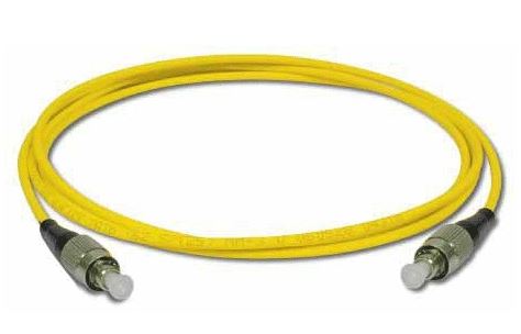
Figure 2: Fiber FC – FC patchcord
Used by the newer equipment are the LC-LC, LC-SC/PC/APC.
The SC/PC connectors are characterized by a polished surface which causes a high-end face resulting in better core connectivity and small optical return loss.

Figure 3: Fiber SC PC connector
The SC/PC features a blue color code.
With a coded green color, the APC connectors accurately have 80 cut in the ferrule and are not capable of exhibiting Fresnel reflection.
With a very low reflection, The APC connectors are the most suitable for bandwidth applications that are on the high side. APC connectors, however, possess higher insertion losses compared to PC connectors. SC is an abbreviation of Standard and Square connectors.
PC is an acronym for Physical contact connectors or polished connectors while APC stands for Angled Physical contact or Angled polished connectors.

Figure 3: Fiber SC APC connector

