ANSI/TIA-568-C.1 requires that any work area should have at least two information-outlet ports.
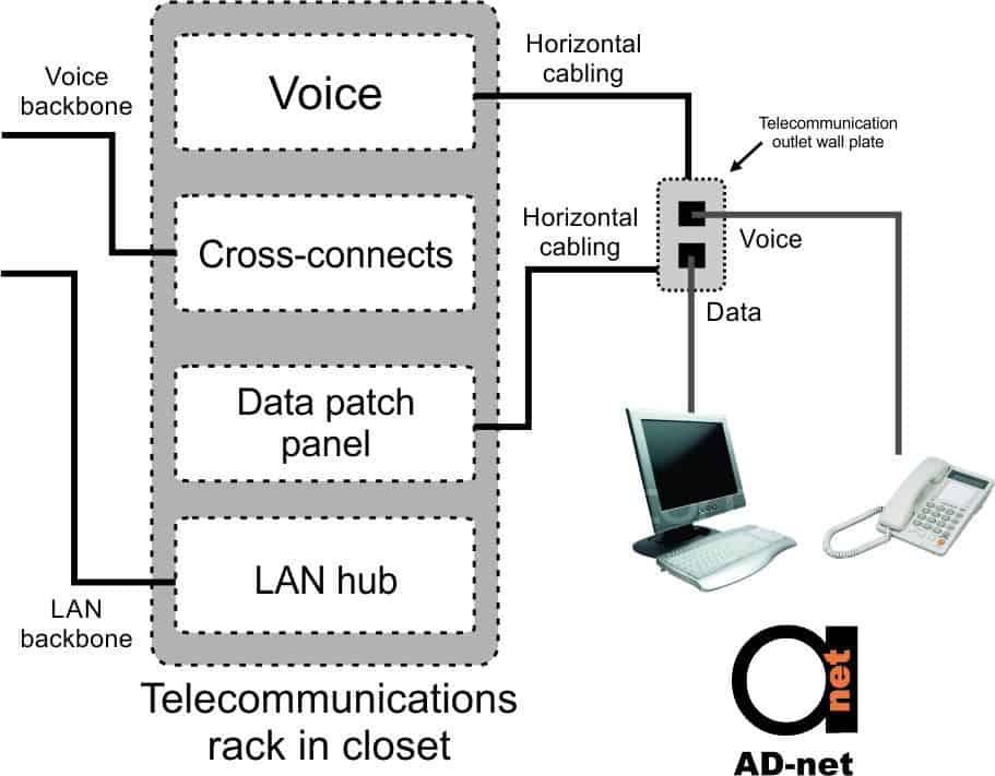
One is typically used for voice while the other is used for data. Figure 1 shows a typical telecommunications outlet configuration.

Figure 1: Typical telecommunications outlet with UTP for voice, and separate UTP/ScTP and fiber for data with backbone cables.
Telecommunications outlets are referred to by various names, including information outlets, equipment outlets, wall plates and wall jacks. An information outlet is however officially seen as one jack on the telecommunications outlet, while a telecommunications outlet is seen as part of the horizontal cabling system.
Information outlet wiring for UTP should follow one of two conventions for wiring patterns or wire-pair assignments: T568A or T568B.
Although these are virtually identical, pairs 2 and 3 are swapped around. Either of these is the correct choice, providing that the same convention is used at both ends of a permanent link. It is of course always best to use the same convention throughout a cabling system. T568B was previously more commonly used in commercial installations, but the recommended configuration nowadays is T568A. As per AN 81/ TIA-57o-B, it is also the required configuration for domestic installations. The T568A configuration is partly compatible with USOC, an old wiring scheme used for wiring voice systems.
Consistency at both the ends of a horizontal cable is key. When patch panels and jacks are purchased, it may be required to specify the pattern that is being used, as the equipment is often color-coded to facilitate easier installation of the wire pairs. Most manufacturers do however include options that allow the configuration to be punched on the jack or patch panel.

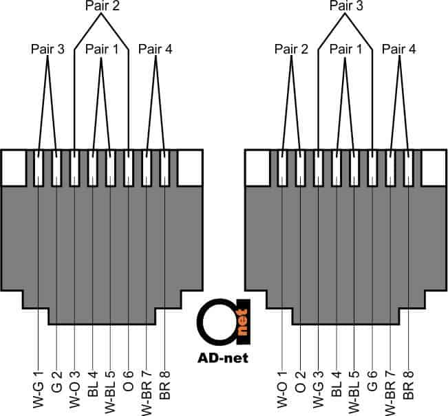
Figure 2 the pinouts for T568A and T568B.
The wire/pin assignments in Figure 2 are designated by wire colors. Standard wire colors are shown in Table 1.
Modular jack wire pattern assignments for T568A and T568B.
| Wire abbreviation | Wire color |
| W/G | White/ Green |
| G | Green |
| W/O | White/Orange |
| O | Orange |
| W/Bl | White/Blue |
| Bl | Blue |
| W/Br | White/Brown |
| Br | Brown |
Table 1: Wire Color Abbreviations
Although an application may not need all the pins in the information outlet, it is always good practice to ensure that all wires are terminated to the appropriate pins, even if it is only done to make sure that future applications on the same media will run properly. Table 2 shows various applications commonly used and the pins that are used. This illustrates clearly why all pairs should be terminated so that the structured wiring installation remains application generic.
| Pair Number | Color code | T568A pins | T568B pins |
| 1 | White-Blue (W-Bl) / Blue (Bl) | W-Bl = 5 / Bl = 4 | W-Bl = 5 / Bl = 4 |
| 2 | White-Orange (W-O) / Orange (O) | W-O = 3 / O = 6 | W-O = 1 / O = 2 |
| 3 | White-Green (W-G) / Green (G) | W-G = 1 / G = 2 | W-G = 3 / G = 6 |
| 4 | White-Brown (W-Br) / Brown (Br) | W-Br = 7 / Br = 8 | W-Br = 7 / Br = 8 |
Table 2: Application Specific pair assignments for UTP cabling
Color Coding and Pair Numbers
In a UTP cable, the conductors are twisted in pairs and these are color coded so that any pair can be identified easily and terminated quickly to the appropriate pins on the connecting hardware e.g. telecommunication outlets or patch panels
With a four-pair UTP cable, each pair is coded with two colors: the ring color and the tip color. In a cable with four pairs, white is used as the tip color for every pair. To ensure that a tip conductor is associated with the correct ring conductor, the tip conductor often has a band of the same color as the ring conductor.
With Category 5e and higher cables, this positive identification (PI) is strictly speaking not required as the intervals between pair twists are so close together that separation is highly unlikely.
Conductors are identified by the color codes, for example as white-green and green. With indoor cables, the tip color is commonly read first, including the PI color, followed by the ring color.
| Application | Pins 1-2 | Pins 3-6 | Pins 4-5 | Pins 7-8 |
| Analog voice | – | – | Tx/Rx | – |
| ISDN | Power | Tx | Rx | Power |
| 10Base-T (802.3) | Tx | Rx | – | – |
| Token Ring | – | Tx | Rx | – |
| 100Base-TX (802.3u) | Tx | Rx | – | – |
| 100Base-T4 (802.3u) | Tx | Rx | Bi | Bi |
| 100Base-VG (802.12) | Bi | Bi | Bi | Bi |
| FDDI (TP-PMD) | Tx | Optional | Optional | Rx |
| ATM User Device | Tx | Optional | Optional | Rx |
| ATM Network Equipment | Rx | Optional | Optional | Tx |
| 1000Base-T (802.3ab) | Bi | Bi | Bi | Bi |
| 10BBASE-T (802.3an) | Bi | Bi | Bi | Bi |
| Bi = bidirectional
Optional = may be required by some vendors |
||||
Table 3: Four-pair UTP color codes, pair numbers and pin assignments for T568A and T568B.


