TDM over IP & E1 over IP – AD-net introduces new concepts of solving the E1 clock recovery problem
It is well known that the E1 signal comes from PCM technology which is TDM in nature. It transmits information in a constant bit rate of 2048kbit/s. TDM technology occupies fixed transmission bandwidth, with QoS features suitable for real-time applications such as voice and video. The QoS features include short and stable transmission delay, low jitter and wander, etc.
On the other hand, Ethernet is based on statistical multiplexing, transmitting and exchanging information in packets. It does not take up a fixed transmission bandwidth, which is good for achieving higher bandwidth utilization. But Ethernet technology does not provide adequate QoS for real time applications.
Until recently, voice and data were, and still are to a large extent, transported over two separate networks. But the requirement for both types of information to be carried over a unified network is growing rapid. Packet over SONET/SDH techniques to integrate date into the TDM network have been around for many years. But for voice over packet based data networks, most of the efforts are spent on creating special equipment that packetizes voice or video signals, such as VoIP techniques.
However, to take advantage of the data network, it is neither cost effective, nor necessary to hastily replace all the TDM based equipment with new packet based equipment. The AD-TDM-IP can be used to emulate transparent E1 channels over an Ethernet with adequate QoS, so that most of the existing E1 based applications can be readily setup over Ethernet LANs and WANs. One particular suited application is to build E1 links with low cost wireless LAN bridges, replacing much more costly microwave radios.
Wikipedia gives following description of TDM over IP format:
Although TDM can be used to carry arbitrary bit streams at the rates defined in G.702, there are standardized methods of carrying bit streams in larger units each containing the same number of bits, called frames. TDM framing locks the frame rate to the sampling frequency of voice traffic, so that there are always 8000 frames per second; a T1 frame consists of 193 bits and a E1 frame of 256 bits.
Unlike unframed TDM for which all bits are available for payload, framed TDM requires dedicating of some number of bits per frame for synchronization and perhaps various other functions (e.g. 1 bit per T1 frame, 8 bits per E1 frame). Framed TDM is often used to multiplex multiple voice channels each consisting of 8000 8-bit samples per second in a sequence of timeslots recurring in each frame. When this is done we have “channelized TDM” and additional structure must be introduced.
In order to efficiently transport slowly varying channel associated signalling bits, second order structures known as multiframes or superframes are defined. For example, for E1 trunks the CAS signaling bits are updated once per multiframe of 16 frames (every 2 milliseconds) while for T1 ESF trunks the superframe is 24 frames (3 milliseconds). Other types of second order structures are also in common use. In GSM cellular networks, the Abis channel that connects the Base Transceiver Station (BTS) and Base Station Controller (BSC) is an E1 link with several framing alternatives, all of which have a basic superframe duration of 20 milliseconds.
The term “structured TDM” is used to refer to TDM with any level of structure, including ‘framed TDM’ and ‘channelized TDM’.
TDMoIP transport is denoted “structured-agnostic” when the TDM is unframed, or when it is framed or even channelized, but the framing and channelization structure are completely disregarded by the transport mechanisms. In such cases all structural overhead must be transparently transported along with the payload data, and the encapsulation method employed provides no mechanisms for its location or utilization. Structure-aware TDM transport may explicitly safeguard TDM structure, in three conceptually distinct ways, which we shall call structure-locking, structure-indication, and structure-reassembly.
Structure-locking ensures that packets consist of entire TDM structures or multiples/fractions thereof. Structure-indication allows packets to contain arbitrary fragments of basic structures, but employs pointers to indicate where the following structure commences. In structure-reassembly components of the TDM structures may be extracted and reorganized at ingress, and the original structure reassembled from the received constituents at egress.
Now, let’s stop on the techiques, which allows us get uniquie clock recovery from IP links.
If you look at the AN-TDM-IP console setiings, There are 8 groups of paired setting i.e. mode 0 and mode 1 define a communication pair, as well as 2/3, 4/5, E/F. The even/odd are paired (1+even=odd). Recommend mode switch setting is 2/3 mode (one side AN-TDMoIP is mode 2, another is mode 3)
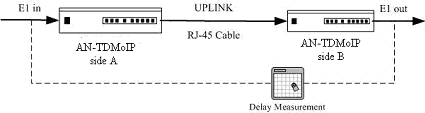
The time delay of E1 link unilateralism rough estimated as follow,
Time delay =X+Y+Z.
X= Fixup delay, about 1.5ms.
Y= Packet delay. If packet size is n×128 byte, then Y≈n/2 (ms)
Z= Jitter Buffer Size delay. The m= Jitter Buffer Size =1~80, Z= m/2 (ms).
Then,
Time delay =X+Y+Z ≈1.5+n/2+m/2 (ms).
For example, mode switch setting is 2/3 mode, packet size is 3×128 byte (n=3), Jitter Buffer Size is 30 (m=30), so Time delay ≈1.5+3/2+30/2 =18 (ms). Mode switch setting is 4/5 mode, packet size is 11×128 byte (n=11), Jitter Buffer Size is 30 (m=30), so Time delay ≈1.5+11/2+30/2 =22 (ms).
If uplink connection uses wireless LAN bridges, the time delay of E1 link unilateralism need add delay of wireless LAN bridges link.
Optimized Jitter Buffer Size is important for TDM over IP link. Increase Jitter Buffer Size will be better to resist packet delay variation (PDV) of LAN bridge, but increase the time delay of E1 link. Decrease Jitter Buffer Size will decrease the time delay of E1 link, but be worse to resist packet delay variation (PDV). Shortage of jitter buffer to resist packet delay variation (PDV) of LAN bridge will cause E1 error bits. More time delay of E1 link will cause low quality of E1.
Also, there are two types of timing mode, through and loop. Both units of AN-TDM-IP are setting to through timing mode works well for all the conditions, although the other option may work better. So, default timing mode through is suggested.
Correct timing mode setting is important for smooth operations. In most cases, setting both units to through timing mode is sufficient. But sometimes, setting one unit to loop timing mode may work better. For example, setting the AN-TDM-IP unit connected with the clock master (such as local exchange, master station etc.) to loop mode, and the other unit connected with the clock slave (such as PBX or remote module, slave station etc.) to through mode, is probably better than setting both to through modes.
Note: setting the AN-TDM over IP unit connected with the clock slave to through mode is important for link synchronization.
So, what the scratch:
- When it comes down to TDM-IP:
- Not a delay itself – PDV – Packet Delay Variation kills most TDM-IP applications;
- Wrong clocking select also makes quality of link worse
- All mechacnical things, like groundings, cable lenghts makes effect on TDM-IP transmission system;

