Let’s say it as it is – single mode fiber now at the time of this writing (April 2017) is a popular choice that is commonly used with communication equipment.
Especially, when we talk about FTTx PON networks – cable that comes from OLT to ONU’s, via ODN with splitters – it’s single and only single mode, no POF, no Multimode is possible.
The extensive use of the single mode fiber by communication engineers can be attributed to its properties that enhance crucial optical performance when it is used. These properties include- attenuation, dispersion and the mode field diameter.
Attenuation
Attenuation is the term that is used to describe the reduction of signal strength or the intensity of the light over the length of the fiber. It is measured in decibels per kilometer (dB/km).
The level of attenuation of light that occurs through a fiber is varied by the wavelength recorded at values of 0.35 db/km at 1300 nm for the single mode fibers and 0.25 db/km at 1550 nm.
Typical attenuation curve for single mode fibers looks like this:

In this condition, the propagation of optical signals through the optical fiber is easily achieved within the range of about 100 km without any form of amplification or regeneration, depending on factors like the type of fiber used, splicing losses, the wavelength transmitted through the fiber and power.
There are two major factors that cause attenuation, they are – scattering and absorption. Scattering of light is caused by molecular level abnormalities that occur in the glass structure.
Absorption losses are experienced due to the material deposits like metals and water ions found within the fiber core and cladding. The presence of water ions has a magnification effect on the light rays being transmitted through the fiber which promotes the losses observed due to attenuation which also affects the wavelengths.
More in-depth discussion about Optical Power Loss in fiber access, you can read here.
Dispersion
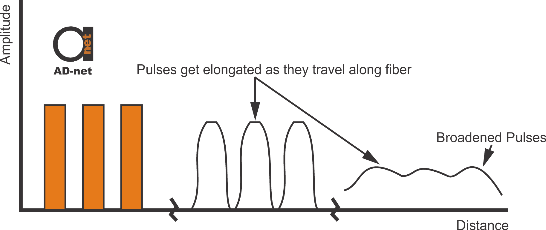
Dispersion can be described as the condition where there is either a widening or an elongation of the pulse.
It happens as a result of the difference in the time at which optical signals comprising of various components are transmitted through the fiber. When this happens during digital transmissions, the occurrence of dispersion reduces the maximum data rate, the maximum distance and the ability of the single mode fiber link to transmit the adequate information.

Figure 2 — Effects of dispersion on an optical fibers performance
The figure 2 shows a vivid illustration of how dispersion influences the properties of the signal being transmitted through the fiber.
It should be noted however that the fiber design has an overall ability to manage the dispersion in a SMF which is varied with the wavelength. The wavelength for which the value of dispersion is equal to zero is known as the zero-dispersion wavelength (0). At this wavelength, the maximum bandwidth capacity that can be handled by the fiber can be tested, for a standard SMF (0) at 1310 nm.
Mode-Field Diameter
The Mode-Field Diameter (MFD) is a functional factor upon which the performance of the optical system is hinged. MFD gives an indication of the effectiveness of the properties a fiber has to enhance the transmission of light. Considering the single mode fibers, this will include a study of the fiber core and the smaller areas of the surrounding cladding glass.
The value of MFD determines how much resistance a fiber will project towards losses experienced from bending and slicing losses. The MFD is best described as a function of wavelength, core diameter and the RI difference that exists between the core and the cladding.
Cutoff Wavelength
The cutoff wavelength is that indicates the wavelength value that must be exceeded for the fiber to transmit only a single mode of light.
Above this wavelength, the optical fiber only permits the single mode of light to be transmitted when a particular wavelength is attained above the cutoff wavelength but below the cutoff wavelength, multiple modes of light will be successfully transmitted.
The length of a fiber ultimately determines its cutoff wavelength; this means a very long fiber will have a lower effective value as its cutoff wavelength. The bend radius of a fiber is known to reduce the cutoff wavelength because bends will shorten the length of the fiber.
Environmental Performance
An important factor that influences the performance of an optical system is the losses that happen as a consequence of microbending.
Microbends are minimal flaws or distortions (changes in the order of the microns) that can be observed along the fiber axis, they are a normal occurrence during the manufacturing process of fiber.
These anomalies create an avenue through which light being transmitted through the fiber is lost. Microbends can also be caused by differences in the coefficient of thermal expansion at low temperatures.
The thermal expansion opens up a space between the core/cladding and the coating materials which leads to an increase in the rigidity of the coating and the cable. The contractions caused by the rigidity will cause more microbends.


